Psychedelic Graphics 0: Introduction
This is an introduction to a series on creating psychedelic-looking visuals, especially for animation and games. It assumes no prior knowledge to working with graphics nor programming, although having exposure to trigonometry and programming will help.
By the end, I hope you will have some understanding of the basics of the psychedelic graphics that I put in my videos. While the majority of those videos were created using Blender, the techniques I teach in this series are easy to transfer over. I will talk about Blender in part 3.
Here's what we're going to build towards in this article and the next one, part 1:
I think the most accessible way for me to convey my techniques is here, on the web. If you're not familiar with graphics programming (or programming at all 😱), fear not! You can still learn a lot! If the code looks like complete gibberish to you, don't look at it for now. Just listen to the sound of my text.
If you don't understand any of the code above... that's expected. I got my start learning graphics programming watching Freya Holmér and it took many hours for me to even understand the fundamentals. Fortunately, you're not here to understand all the fundamentals... you're just here to make things look weeeeird.
What is UV?
3D models
Although computer graphics often look 3D, when you write graphics code, you often have to think in 2D. Let's say you've 3D modeled a beautiful shape in your favorite 3D editing program. What you've really done is created a bunch of points (vertices) floating in space and then connected some of them into solid shapes (faces). It's completely hollow; we only see the surface.
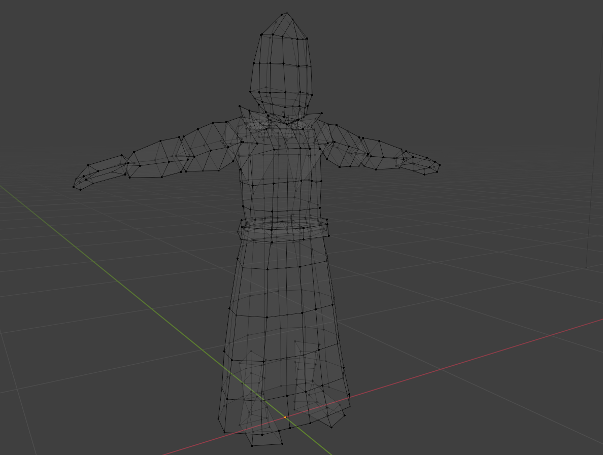
A 3D model (Blast Judgment)
Almost all 3D shapes in video games and animation boil down to this. If it looks smooth, chances are there are just so many points and faces that you can't even tell where one starts and another ends. Now what do we do with these points and faces? How do people make them look alive with contours, and ruffled clothing, and color?
There are actually a few ways to do that. We're going to talk about the standard way to add color to 3D surfaces: UV mapping/texturing.
When you look at a 2D projection of the Earth, it looks a bit stretched and squished in some areas.
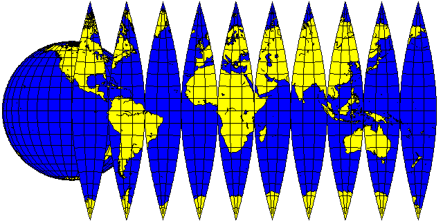
The 2D projection of the Earth (quadibloc.com)
Similarly, when you look at the 2D projection of the colors on a 3D model, it also looks a bit... stretched and squished:
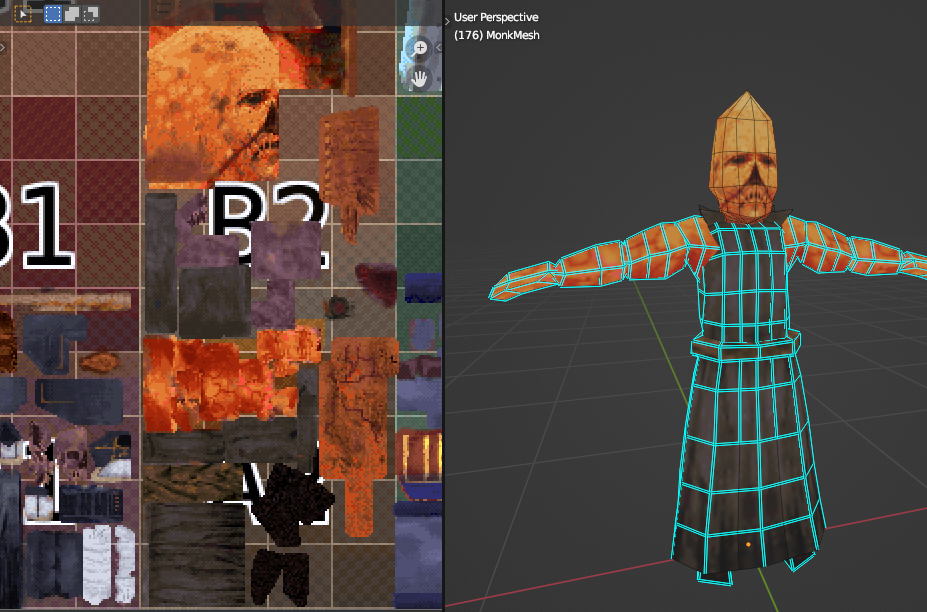
3D model (right) and an image representing its colored faces in 2D (left) (Blast Judgment)
Above, the left side shows the squished, unrolled, 2D images that hold the colors we will eventually put on the surface of the 3D model. That's called the “texture”. One way to create such an image texture is to start by creating a blank image file on our computer. Next, for each face on the 3D object we modeled, we will choose a part of the image texture (the file we just created) for that face.
Selecting faces on 3D model (right) to see its location on the texture (left) (Blast Judgment)
If we reserve the same area for different faces on the 3D model, that's fine. That's very common. For example, if the body is symmetric, we only need to color half of it and then reserve the same parts of the image texture for the faces on both sides. The part of the image texture we reserve for each face can be big or small. And it doesn't need to be the same size or proportions as the face.
Changing the reserved part on the image texture (left) changes how it looks on the model (right) (Blast Judgment)
Painting textures
Next, paint. Anything you paint on the texture shows up on the 3D model.
Painting a texture and seeing it show up on the 3D model (Blast Judgment)
Also, most software lets you paint directly on the 3D model, coloring the image texture for you.
Painting a 3D model and seeing it show up in the image texture (Blast Judgment)
UV coordinates
What are these reserved parts for each face on the 3D model called? They're called UV maps. They are the data that connect parts of the image texture to the 3D model. What is a UV? You can think of a UV as a location on the image texture, a 2D coordinate... let's call the two dimensions X and Y, the common names when you have two dimensions [0]. In this system, (0, 0) is a UV coordinate (X and Y are both 0) and (0.5, 0) is also a UV coordinate (X is 0.5, Y is 0).
Each face on the 3D model has several points that define it and each of those points is placed on the image texture to reserve the area. On the image texture, each of these points have an X and Y location... a UV coordinate!
What are the two numbers in the UVs? They're not random. Let's say a point has the UV coordinate (0.5, 1.0). The horizontal/X value, 0.5, means that the coordinate will be halfway between the left and right sides of the image. The vertical/Y value, 1.0, means that it will be all the way at the top. Both values go from 0.0 to 1.0. It's as if you take the whole 2D number space and zoomed in on the box surrounding (0, 0) and (1, 1).
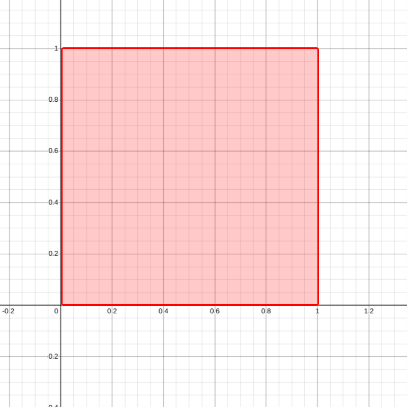
We'll be primarily using the number space within the red box ((0, 0) to (1, 1)) (Desmos)
Why do we use 0.0 and 1.0 and not, for example, the pixel locations on the image? As you learn more graphics, you will find 0 and 1 everywhere and understand more and more. You can think of 0 as saying “not at all” and 1 as saying “yes, completely”. For UV coordinates, 0 to 1 means how far is the point to the right (X) or how far is it to the top (Y). If it helps, you can multiply them by 100 in your head to get a percentage, which has the same meaning (e.g. (0.5, 1.0) is 50% from left toward right, 100% from bottom toward top).
How graphics code works
Colors in graphics
Computer graphics colors are often represented with RGB... red, green, and blue. Basically any color that humans can perceive can be created from a mixture of these three colors. For a single color in computer graphics, the amount of red, green, and blue usually spans from... 0.0 to 1.0. The color red is (1.0, 0.0, 0.0) (100% red, 0% green, 0% blue). Black is (0.0, 0.0, 0.0) (all colors absent) and white is (1.0, 1.0, 1.0) (all colors fully present). If you have made graphics for the web, you may be used to colors like 0xff0000. That's hexadecimal, a different representation, but it conveys the same thing. This interactive example below is just to show the RGB values; don't feel like you have to read the code.
Oftentimes, it can help with visualizing and troubleshooting to look at the color of each UV coordinate. So what color are the UVs? Weird question, right? The convention is to use the first value of the UV (the X value) as red, and the second value (the Y value) as green. And then blue... forget blue. Don't include that. Nobody likes blue (we set it to 0.0). So a UV coordinate of (0, 1) will look end up as the color (0.0, 1.0, 0.0) and look green. A UV coordinate of (1, 0) will be visualized as the color (1.0, 0.0, 0.0) (red).
As you are trying to develop this intuition, just say “RGB” in your head: red, green, blue. Red is first, then green, then blue. Remember I said that the first number of the UV represents left-to-right location and the second represents bottom-to-top location. So, if we color a rectangle as if it's an image texture, using where each UV coordinate is on the screen to determine its color, we end up with this interesting gradient:
When we write computer graphics code, uv.x will give us the X value of the UV and uv.y gives us the Y value. Note in the gradient, as the UV coordinates get closer to the top left (UV coordinate (0, 1)), it becomes more green because the UV (0, 1) becomes the color (0.0, 1.0, 0.0) (that middle 1.0 is the amount of green). On the bottom right, UV coordinate (1, 0) is red (1.0, 0.0, 0.0). Think about why the bottom left is black and the top right is yellow (in computer graphics, what is yellow a mixture of 🤔?):
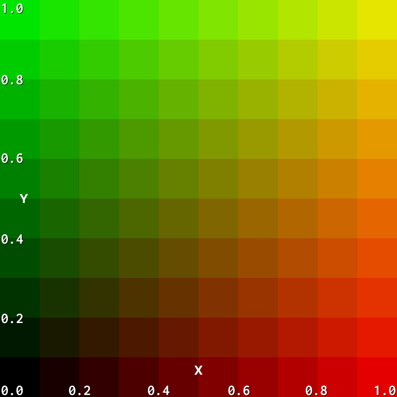
A reference to help visualize what the UV coordinates look like as colors
floats and vectors vec2 vec3
We are going to start talking about the code. Up to this point, I haven't really explained any of the code examples and glossed over all these float, vec2, vec3 words. A float is basically a single decimal number (floating point number). “vec” stands for “vector” and if you're not familiar with this from math, a vec2 is just a pair of decimal numbers, while a vec3 is a triplet of decimals. So our RGB color was a vec3 because it had three decimal values (the numbers that say how much red, green, and blue there is in the color). The UVs are vec2 because they have two decimals, one for X and one for Y.
The structure of graphics programs
We won't be using a 3D model. For all the code examples in this article series, I've created a single 3D face that takes up the entire screen (the square box on the right of each example). But there's no image texture that adds colors. Instead, we are determining the colors on the image texture using code. It's as if I point to each spot on the square box, tell you what the UV coordinate is (between (0, 0) to (1, 1)), and you use the code to freely decide what color it should be.
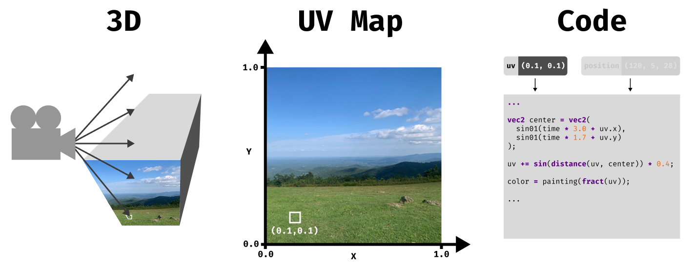
The camera in our 3D scene figures out which parts of the 3D faces are visible. Next, it uses the parts of the image texture we reserved for each face (the UV mapping) to calculate its UV coordinate. Finally, it gives this UV coordinate (and other information like the 3D position) to our code and our code determines the color
This is effectively what's happening in graphics, millions of times per second. But if there are no 3D models, then how are we going to create something cohesive, like a circle or line? Computer graphics can be a bit different than you might be used to in similar areas like like graphic design. You're not drawing a continous line from one point on the screen to another; instead, it's as if spots are chosen at random and I'm asking you to tell me the color. Pretend the code below is not there and just look at the visualization on the right:
In order to carry out plans to create big, interesting designs, graphics require you to “coordinate” in a decentralized way. You can't even look at what color the other parts of the screen are because, for all you know, you haven't even gotten to them yet. The code that you'll write won't just run once to generate all the colors; the code will run for each small part of the screen (each pixel). Even if you have experience programming, computer graphics requires a different mindset.
OK! You're ready to start part 1! You will see how we create interesting interesting visuals even with these constraints in part 1.
Curious about hiring me or working together? Check out my hiring page. You can also hear more from me on YouTube or Twitter.
Footnotes
- [0] Actually, the two dimensions are called U and V because X, Y, and Z are already taken by the 3D position. Since we're not concerned with that here, I thought X and Y would be easier to understand.